Variable speed gear box Fluid Couplings Torque Converters for automotive applications. Locate and secure components in an appropriate manner and in their proper position.
What Is Gearbox Types Parts Working Images Pdf
The gear number 11 is pressed on the shaft.
. Things should be made as simple as possible but no simpler This book is an attempt to apply that principle to gear design by presenting information from a manufacturing point-of-view rather than a theoretical one. Constant mesh gear box - Speed reducer unit. To we engage the 2nd gear we move the lever like in the last image and the gear selected fork will engage the collar in the 2 nd spur gear blue.
It has three shafts. Gear design is a highly complicated art. When the collar engages in the any spur gear there will be a transfer of rotation between spur and differential and now we have rotation in wells.
Small gear driving large gear Under Drive Under Drive happens when Carrier is the Output Under drive increases Torque decreases Speed Large Gear driving Smaller gear Overdrive Overdrive happens when the Carrier is the Input. IJSRD - International Journal for Scientific Research Development Vol. The strength design of the gear to allow for the use a Grade 1 steel.
Each detection technique has its own advantages and limitations. To ensure capable processes this includes considering both process design considerations and established business requirements. Types-pressure angle and under cutting base circle determination-forces and surface stresses.
At the very least the same setup could be used but. It may be a gearbox a torque converter overdrive fluid drive or hydraulic drive. Rotating Elements ie gears sprockets pulleys etc 3.
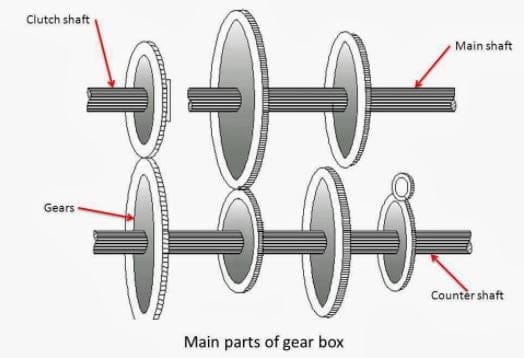
5 hp with 1800 rpm Capacity. The most popular design is the constant-mesh gearbox. The input shaft the layshaft and the mainshaft which run in bearings in the gearbox casing.
Gear box finds its application in Agitators conveyors crushers cranes elevators feeders small ball mills mixers cooling towers Extruders Packaging and Filters. A part of the shaft is a wheel of parking pawl. Up to 24 cash back 2.
This chapter begins with a comparison of the merits of spiral bevel gears and hypoid gears when employed as the final drive in the automotive gearbox ix. Gearbox in automobile. Volume 20 2017 Pages 544-549.
Introduction to Gear Design Introduction Albert Einstein once said. A design methodology also aids in training new manufacturing engineers. And it is intended for the reader to use his own experience in selecting formulae stress values etc.
While the transmission is in gear as engine speed increases torque is transferred from the engine to the input shaft by the motion of the fluid propelling the vehicle. 5 Issue 08 2017 ISSN online. Study and Sectional View of Differential Gear- Mechanical Projects.
Design and Fabrication of Progressive Gearbox Report Download. Machine Design Project Report Semester 1 20142015 Group 3B1 4 fDESIGN SPECIFICATIONS Motor. The first shaft of designed gearbox was designed to manufacture.
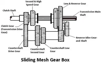
Types Of Automobile Gearbox Working of Sliding Mesh Gearbox. Gearbox Design Layout only Gearbox Design Issues. 2321-0613 Automobile Transmission Systems Suyash Galgale1 Prathamesh Deore2 Ketan Pardeshi3 123 BE Student 123 Department of Mechanical Engineering 123 University of Pune Nasik India Abstract In the current world of automobile gear shifting equipped with an.
The gear lever operated by the driver is connected to a series of selector rods in the top or side of the gearboxThe selector rods lie parallel with shafts carrying the gears. UNIT V CAMS CLUTCHES AND BRAKES 9 Cam Design. There are no great advances in gear technology described.
Each of the chapters will deal with a-specific problem which is encountered during the design phases and during operation. Gearbox Design Machine Design- Interview Question and Answers. What is gearbox or transmission.
DESIGN OF AN AUTOMOTIVE DIFFERENTIAL WITH REDUCTION RATIO GREATER THAN 6. And the same principle applies to the other gears. It also involves almost all stakeholders gearbox OEMs turbine OEMs ownersoperators research institutes governmental agencies and so on.
This system was used as a baseline to which other designs were compared. By using the given rotational speed of 1800 rpm input power of 10 horsepower gear ratio of 35 and an overload factor of 15 the rough dimensions of the gear and pinion were determined. The second shaft was adapted for design purposes before heat treatment.
System Design 21 Powertrain layouts The previous powertrain design consisted of two Emrax 228 motors each with a chain drive single gear reduction to independently drive the rear wheels. O In automotive applications the pump typically is connected to the flywheel of the engine The turbine is connected to the input shaft of the transmission. When the engine is running and the car is stopped the stator will lock on the One Way Clutch.
By providing a checklist and ensuring customer needs are considered a methodology directs design efforts in the most productive direction. Introduction and Purpose Provides speed and torque conversions because of the limitations of internal combustion engines. Transmission shafts or just shafts are used in virtually every piece of rotating machinery to transmit rotary motion and torque from one location to another part of machine.
Also facilitates change of direction of output shaft for reversing Automotive gearboxes are used to reduce load on the engine by manipulating torque and speed. New Design of the Automobile Automatic Gearbox Providing Driving Simplification and Driver Fatigue Decrease. The constant pressure to build less expensive quieter running lighter and more powerful machinery has resulted in a steady change in gear designs 3.
Design of a manually operated automotive gearbox. The purpose of this booklet is to set out the basic design for an industrial gearbox. Holistic approach involving design manufacturing testing packagingshippinghandling installation operation and maintenance.
The word transmission is used for a device that is located between the clutch and the propeller shaft. Position of the fourth gear next to the final drive was possible to use the second shaft of the gearbox MQ200. At present much is known about gear load-carrying capacity and many complicated processes for making gears are available.
Up to 24 cash back With these major changed to the design the gearbox is still operating well and safely according to the theoretical calculations. It should help students not familiar with gearboxes lay out a reliable working design.
Gearbox Definition Parts Or Construction Working Types In Detail Function Purpose Advantages Application Notes Pdf
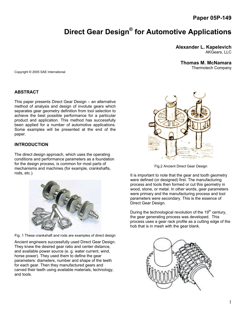
Pdf Direct Gear Design For Automotive Applications

Visualization Of Gearbox Design Parameters Variables Description In Download Scientific Diagram
2
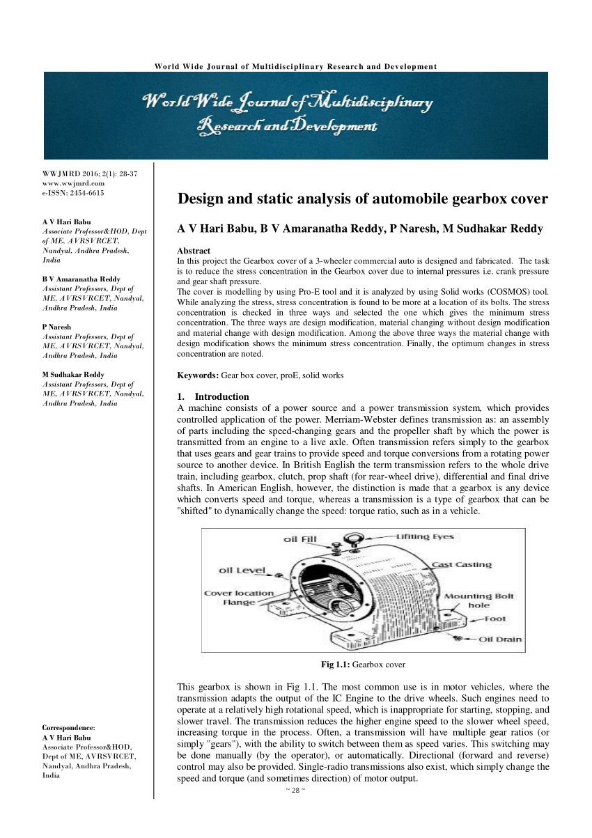
Pdf Design And Static Analysis Of Automobile Gearbox Cover

Pdf Design And Analysis Of 9 Speed Gearbox

Design And Fabrication Of Gear Box Full Report Download

Constant Mesh Gear Box Design Of Transmission Systems
0 comments
Post a Comment